INSTRUCTION MANUAL LEDO-IM-001 / Rev 0.1 / 15 Oct 2026
DRAFT - NOT FOR RELEASE. Reformatted from the existing Instruction Manual with manufacturer-confirmed IP65, 14-bit output and functional-earth information. Unresolved ratings, installation drawings and release documentation require approval.
LED_O
Instruction Manual
Installation, commissioning, operation and maintenance of the industrial machine-status display.
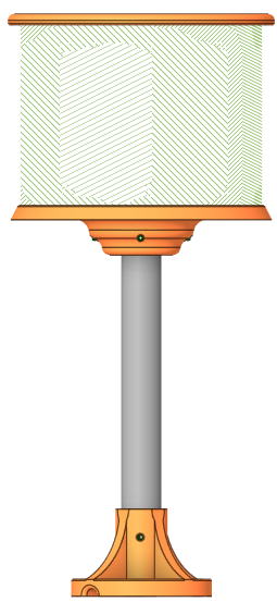
Illustrative product rendering
1. Intended use and safety
LED_O provides visible status, messages, graphics and process information for machinery, production equipment and process installations. A compatible PLC can control the device over Modbus TCP; a browser interface supports commissioning and display configuration.
Installation and electrical work must be performed by competent personnel using appropriate isolation and safe working procedures.
Use only the specified 24 V DC supply. Do not connect the device directly to mains voltage.
Keep power isolated during wiring, mounting, inspection and cleaning. Verify the installation before energising.
Do not modify the enclosure, internal wiring or protective circuitry. There are no user-serviceable internal parts.
Confirm suitability for the application, environment and mounting arrangement before use. Remove damaged or faulty equipment from service.
Indication, not a safety function: do not rely on LED_O as the sole means of warning where missed, incorrect or lost indication could create a hazard. The machine integrator must provide appropriate independent safety measures.
The green conductor is functional earth for EMC return paths, not a protective-earth safety connection. This manual does not assign a SELV/PELV category or electrical protection class. See page 4 for connection details.
MES LED_O
PRE-USE CHECKS / LIMITS DRAFT - NOT FOR RELEASE
2. Pre-use checks and operating limits
Unpack and inspect
Check the main unit, diffuser, mounting assembly and cables for damage, loose parts or signs of moisture ingress.
Check the supplied power and Ethernet cables and any accessories against the ordered configuration. The source manual describes nominal 3 m cables; confirm the supplied variant.
Verify that model identification, serial number and fitted labels are present and legible. Check regulatory marking against the actual release status.
Do not install missing, damaged or unidentified parts. Contact the supplier before putting the product into service.
Electrical and environmental limits
Supply
24 V DC ±10%; confirm final approved operating limits
Current consumption
Instruction Manual: 1.25 A maximum; Quick Start Guide: 1.1 A. Confirm final rating and conditions before supply/protection selection.
Internal power protection
Reverse-polarity, over-current and over-voltage protection; external circuit protection remains required
Operating temperature
0°C to 60°C
Storage temperature
-40°C to 85°C; source quick-guide value pending approval
Relative humidity
30-90% RH, non-condensing; source quick-guide value pending approval
Ingress protection
IP65: dust-tight and protected against water jets. Not suitable for immersion.
Enclosure
ABS with polycarbonate diffuser, per product specification; confirm production materials
Product reference
Display / colour output
32 × 124 RGB pixels / 14-bit output
Pixel pitch / brightness
3 mm / 800-1200 cd/m² after diffuser, source product values
Dimensions / mass
100 × 428.5 × 100 mm (W × H × D) / 1.25 kg; confirm mounting assembly and included hardware
Communication
Ethernet; Modbus TCP; HTTPS browser interface
Source conflicts requiring approval: the original manual includes a separate 5 V, 64 × 32, 4 mm-pitch panel specification, different brightness/lifetime values and inconsistent voltage endpoints. These must not be treated as finished-device ratings. Confirm environmental, vibration and drop-test claims against the actual tested assembly.
MES LED_O
MECHANICAL INSTALLATION DRAFT - NOT FOR RELEASE
3. Mechanical installation
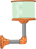
Install the pre-assembled body using the mounting arrangement supplied for the ordered configuration. The source describes vertical-post and offset-post arrangements. Confirm the approved orientation and mounting method for the actual unit.
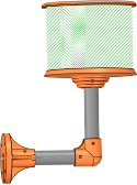
Wall-bracket arrangementBracket detail
Mounting procedure
Isolate power and make the host equipment safe before installation.
Select a rigid support and position that gives operators a clear view without obstructing controls, guards or access routes.
Use the approved dimensioned drawing to establish mounting holes, fixing selection, clearances and tightening requirements. Do not scale the illustrations.
Secure the mounting assembly and check for movement. Do not drill the enclosure or alter factory cable entries.
Route and support cables so they cannot be pulled, pinched, cut or repeatedly flexed at the entry point. Observe the supplied cable's bend-radius and environmental limits.
Check diffuser, covers, cable entries and mounting condition before connecting power. Maintain the installation conditions required for IP65.
IP65 is not an immersion rating. Do not submerge the device. Do not infer suitability for high-pressure or high-temperature washdown, chemical cleaning or outdoor exposure from IP65 alone; confirm additional environmental requirements for the application.
Drawing approval
The original Word documents contain mechanical illustrations, retained in the original Instruction Manual and original Quick Start Guide. This HTML draft uses product renderings, not manufacturing drawings. Approved hole positions, fastener details, torque values and cable-clearance dimensions must be inserted before release.
MES LED_O
POWER / ETHERNET / EMC EARTH DRAFT - NOT FOR RELEASE
4. Power, Ethernet and functional earth
LED_O is a low-voltage device powered by 24 V DC. Connect the brown conductor to +24 V DC and the blue conductor to 0 V DC. The green conductor provides functional earth (FE) for EMC return paths, not protective earthing for electrical safety.
Connection overview, not a connector pinout. Use a PC instead of the PLC for browser commissioning. FE is shown separately from the 0 V supply return.
Connection procedure
Isolate the supply and verify conductor identification against the supplied unit.
Provide suitable external overcurrent protection for the cable and installation. Final current rating and protective-device selection require approval; no fuse value is specified here.
Connect +24 V, 0 V and functional earth as above. Use the manufacturer's approved EMC earth/bonding arrangement; do not assume FE can be omitted because the supply is low voltage.
Connect the supplied RJ45 Ethernet cable to the commissioning PC or automation network. Support the cable and prevent accidental disconnection.
EMC installation precautions
Route power and communication cables separately where practicable. Avoid unnecessary cable length and loops; keep clear of drives, contactor switching loops and high-current conductors. Different cable types, lengths, bonding or host equipment may change EMC performance. Confirm the tested installation arrangement with the formal laboratory report.
The source describes nominal 3 m power and Ethernet cables and a 0.5 mm² three-core power cable, but cable type labels differ between sections. Confirm the production cable specification, terminations and bonding details before release.
MES LED_O
COMMISSIONING / OPERATION DRAFT - NOT FOR RELEASE
5. Commissioning and operation
Before applying power
Check mounting security, enclosure condition, supply polarity, the functional-earth EMC connection, cable support and the host machine's safe state. Confirm the supply and installation meet the approved ratings.
Factory network settings
IP address
10.0.0.49
Subnet mask
255.255.255.0
Gateway / DNS
10.0.0.1 / 10.0.0.1
Browser access
https://10.0.0.49 from a PC on the same subnet
First connection
Connect one factory-default unit at a time on an isolated commissioning network. Set the PC to an unused address, for example 10.0.0.100 / 255.255.255.0.
Apply 24 V DC. A network-disconnected message may appear when Ethernet is absent; it does not by itself indicate a hardware fault.
Open the device address in a compatible browser. Verify device identity and follow the approved certificate procedure if prompted. Do not globally disable browser security.
Use manufacturer-provided credentials where required. Set a unique operational IP, record the change and reconnect at the new address. Change default credentials where supported.
Use the browser Control page to show a short message such as READY. Select a visible colour and verify the physical display. Confirm save/apply behaviour on the installed firmware.
Before PLC integration, use the Programming Manual to check addressing, supported register groups and data formats. Do not issue trial writes on an operational machine.
Routine operation
Verify that text, process values, colours and alarm messages match the host equipment state. Ensure indications remain visible and meaningful to the operator. Investigate frozen, incorrect or missing information; do not assume the displayed value proves that communication is healthy.
Loss of communication: do not assume automatic blanking, a watchdog or a defined alarm state. The integrator must test the device response and provide an appropriate fault indication in the overall machine control system.
The original quick guide also lists 192.168.1.50; 10.0.0.49 agrees with the Instruction and Programming Manuals and the quick guide's separate network table. Confirm the factory configuration on the release firmware. Do not expose the device directly to the internet.
MES LED_O
MAINTENANCE / SUPPORT / RELEASE DRAFT - NOT FOR RELEASE
6. Maintenance and support
Cleaning and inspection
Isolate the power supply before cleaning. Clean external surfaces with a dry or slightly damp, non-abrasive cloth. Do not use solvents, aggressive chemicals or excessive moisture. Do not open the enclosure. Use suitable ESD-safe handling methods where required.
At intervals appropriate to the application, inspect mounting security, cable support, diffuser condition, enclosure integrity and label legibility. Check that displayed information and the functional-earth EMC connection remain correct. No fixed inspection interval is established by the source manual.
Basic troubleshooting
Symptom
Action
No display
Make the equipment safe; have competent personnel check the 24 V supply, polarity, wiring and circuit protection. Do not bypass protective devices.
Browser unavailable
Check Ethernet, assigned IP, subnet, duplicate addresses and HTTPS/certificate handling.
PLC control unavailable
Check Modbus port 502, client connection limits, addressing and the register/function combination. See the Programming Manual.
Incorrect or stale indication
Check host data and communication health, display settings and competing browser/PLC updates. Do not treat the indication as a safety function.
Damage or moisture ingress
Remove from service, isolate power and contact the manufacturer. Do not attempt internal repair.
Repair, storage and disposal
There are no user-serviceable internal parts. Contact the manufacturer for repair or replacement. Firmware updating is described as an internal service-tool operation; obtain approved instructions rather than attempting an undocumented update.
Protect the unit from moisture, mechanical damage and cable strain during storage and transport. Verify approved storage limits before extended storage. At end of life, follow applicable electrical/electronic waste requirements and local collection arrangements; do not dispose of it as ordinary household waste where separate collection is required.
Compliance and controlled release
The manufacturer reports that EMC testing has passed; formal laboratory documentation is pending. Exact test standards, editions, levels and conditions must be taken from the issued report. This draft does not claim completed CE/UKCA marking or replace the applicable Declaration of Conformity.
Before release: approve current and voltage limits, materials, cable specification, EMC bonding details, dimensioned drawings, environmental/test claims and firmware commissioning steps. Complete the controlled compliance documentation and product labels. The source Word manual's protective-earth/Class II wording is superseded here by the manufacturer's functional-earth clarification.
Contact mes@led-o.ddns.net with the model, serial/reference, firmware version, installation details and fault description. Keep passwords and other credentials out of support messages.